This is my technique for rendering large scale terrain using XNA (also applies to DX9 with SM3.0)
Quick Recipe
- At startup create or load two triangle shaped planar meshes (pizza slices)
- Each frame position and orient these meshes to cover the terrain area visible in the view frustum
- In the vertex shader transform world-space positions into texture-space, sample the height map using VTF (Vertex Texture Fetch) and displace the height of the mesh
- Use Catmull-Rom interpolation to determine the heights of mesh vertices that lay between height texels
- Use Uniform Basis Spline interpolation to create perfectly smooth normals
You have a simple and efficient large scale terrain renderer which uses almost no CPU, no CPU-to-GPU bandwidth, and is very GPU friendly! There is no need for quadtrees, octrees, clipmaps, roam or dynamic mesh generation.
Overview
My goal was to render large-scale high-quality terrain with the simplest and most efficient approach possible.
I have read many papers about terrain rendering and they all seem very over-complicated.
One technique that caught my eye was “projecting screen space grid into world space” which is often used in ocean rendering. This uses the absolute minimum no of vertices but, for terrain, suffers from terrible shimmering.
This taught me that the height map, terrain mesh and world space had to align at all times.
(Imagine that the height texture is placed into world space – creating a uniform grid of height points, the mesh must always snap to this grid)
Intersecting the view frustum with a plane is trivial – for the typical case the resulting shape is a triangle … why not create a single triangle-shaped mesh and rotate it around the camera?
I found that two 22.5 degree “pizza” slice shaped static meshes could be positioned around the camera and cover the full 360 degrees.
I use VTF (Vertex Texture Fetch) with a height map to displace the vertices vertically.
By building the static meshes in blocks in near-to-far order it is possible to limit the triangles rendered to the visible bands by using the vertex offset and count.
This approach also plays nicely with the depth buffer and hierarchical & early z culling etc.
What about Level-of-Detail (LOD) ?
As the meshes will always be rendered in near-to-far order, the distance based LOD could be static.
Because the LOD transitions are known in advance there is no need for LOD stitching etc.
Thanks to jwatte on the XNA forums I read "Computer Graphics Principles & Practices" and found that the bicubic surface equations worked perfectly with HLSL as a cubic equation can be solved with a dot product … and a bicubic surface can be interpolated by multiplying a 4×4 geometry matrix with a 4×4 basis matrix etc.
In other words bicubic interpolation was going to be FAST! Sampling 16 8 bit height texels can’t be that expensive …
It also had a great by-product – the same height data and cubic coefficients could be used to calculate slopes and then surface normals.
The end result is: whilst other techniques waste time, resources and bandwidth trying to optimize the mesh – my technique has already finished rendering.
Implementation
Create two static planar triangle-shaped meshes:
One for 0 to 22.5 degrees:

One for 22.5 to 45 degrees:

Note! The right hand edge of the second mesh is a straight line:
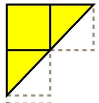
For squares which overlap both meshes – the mesh which includes the center point (or the left mesh if that is both) takes the square.
Tesselation
Each numbered cell in the above meshes is tesselated according to its LOD band.
The meshes are tesselated like this:
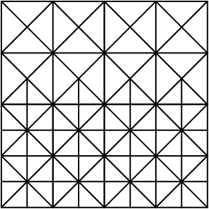
Which means there is no need for LOD stitching, and the mesh looks the same when rotated by a multiple of 90 degrees etc.
Unit Transformation
Use a 2×2 unit transformation matrix to reflect / rotate the meshes around the mesh origin:
![]()
Get a height map
8 or 16 bit grayscale

I use Alpha8 DDS with 8192×4096 resolution.
Vertex Buffer
I created a function that creates the terrain meshes using parameters for size, no of lod levels and position of lod transitions.
The function builds the mesh in left to right, near to far order and records the vertex number of the start of each row.
The vertex numbers are used to draw only the visible rows.
Example:

In the above diagram only rows 2 to 13 inclusive are visible.
Vertex Buffer continued
Use the VertexElementFormat.Short2 (ushort) format to reduce the size of each vertex to only 32 bits (and therefore use integer coordinates for the vertices)
You can put both meshes in a single vertex buffer – as long as you keep track of the vertex offsets. (This saves the expense of switching vertex buffers during drawing)
With this approach we can fit 8 vertices into 32 bytes.
Decide scales
The object space mesh must fit the view frustum without any gaps.
Use the Far Plane to calculate a scale factor that ensures that the shortest side of the mesh (taking into account position rounding) is longer than the longest line in the view frustum (from near top left to far bottom right)
LODs and Interpolation
There should be a 1:1 Vertex:Texel ratio at the lowest resolution LOD level.
As the resolution increases so will the number of vertices per texel.
The heights of the intermediate vertices (between height texels) are calculated using a Catmull-Rom or Basis Spline (BSpline) bicubic surface.

Geometry Implementation
Origin Determination
To stop shimmering the mesh and height map must be fixed in world space
That means we need to round the world space origin of our terrain slices:
– Project the view space Z axis onto the terrain plane
– Find the nearest height point in the opposite direction
– Use this as the mesh origin
Note! This is the location of the nearest height map texel, behind the camera, in world space.
Frustum Culling
– Project the view frustum on to the terrain plane
– Calculate the slices which intersect
– Calculate the near and far rows that are visible
– Repeat for 3 or 4 terrain planes between min and max height (y = 0%, y = 25%, y = 50%, y = 75%, y = 100%)
– For each visible slice define the unit 2×2 transformation and the vertex offset and count
What about looking vertically down?
If you are close to the ground then looking down will result in all 16 slices being rendered.
But the number of vertices will be low due to the small no of visible rows.
As the camera’s height increases this can lead to all 16 slices being rendered in full – too many vertices!
A solution is to either clamp the camera’s height or to scale the mesh up by powers of 2 as the height increases (Vertical LOD?)
Vertex Shader Implementation
Effect Parameters
The vertex shader needs:
float    VertexSpacing;     // world distance between vertices (at highest resolution lod level) (Example 1.0)
float    TexelSpacing;      // world distance between height texels (Example 4.0)
float3   TerrainOriginInWorldSpace; // rounded world space position of terrain origin
float4   UnitTransform;     // 2x2 transformation matrix used to orient current slice into world space
float4x4 matView;           // standard view matrix
float4x4 matProj;           // standard projection matrix
You can convert the float4 in HLSL like this:
static const float2x2 mat2x2 = (float2x2)UnitTransform;
then use it:
float2 Ptransformed = mul(Pmesh, mat2x2);
Transformation
– Orient the slice using the Unit Matrix
– Scale the slice into World Space
– Translate the slice into Position using TerrainOriginInWorldSpace
Vertex Texture Fetch
Transform the world space position into height map texture space and use VTF Vertex Texture Fetch to read the height:
float2 texHeight = WorldSpaceToTextureSpace(posWorld.xz);
float height = tex2Dlod(smpHeightMap, float4(texHeight, 0, 0)).r;
Cubic Interpolation
This diagram shows Linear, Catmull Rom and BSpline interpolation:

Linear is just straight lines which will look horrible
Catmull-Rom interpolates exactly but can wobble
BSpline doesn’t interpolate exactly but is perfectly smooth

The graph above of the Catmull Rom second derivative shows that surface is not perfectly smooth
compare with graph of BSpline second derivative:

You can use either scheme – as long as your terrain collision uses the same.
For per-pixel normal calculation bsplines give C2 continuity aka “perfectly smooth”.
Some CSharp code to perform cubic interpolation:
public static Matrix MatCatmullRom =
    new Matrix(
        -0.5f,  1.0f, -0.5f,  0.0f,
         1.5f, -2.5f,  0.0f,  1.0f,
        -1.5f,  2.0f,  0.5f,  0.0f,
         0.5f, -0.5f,  0.0f,  0.0f);

public static Matrix MatBasisSpline =
    new Matrix(
        -1,  3, -3,  1,
         3, -6,  0,  4,
        -3,  3,  3,  1,
         1,  0,  0,  0) * (1.0f / 6.0f);

public void CubicInterpolation(
        ref Matrix MatCubic,
        ref Vector4 Geometry,
        float IP,
        out float Height,
        out float Slope) {

    Vector4 T = Vector4.Zero;
    Vector4 ABCD = Vector4.Zero;

    // Calculate Cubic Coefficients
    Vector4.Transform(ref Geometry, ref MatCubic, out ABCD);

    // T Vector
    T.W = 1;
    T.Z = IP;
    T.Y = T.Z * T.Z;
    T.X = T.Y * T.Z;

    // Solve Cubic for Height
    Vector4.Dot(ref T, ref ABCD, out Height);

    // T Vector for Derivative
    T.W = 0;
    T.Z = 1;
    T.Y = 2.0f * IP;
    T.X = 3.0f * IP * IP;

    // Solve Quadratic for Slope
    Vector4.Dot(ref T, ref ABCD, out Slope);

}//method

// Usage:
float Height;
float Slope;

Vector4 Heights = new Vector4(0, 1, 2, 1);

for (float ip = 0.0f; ip <= 1.0f; ip += 0.1f) {

    CubicInterpolation(ref MatCatmullRom, ref Heights, ip, out Height, out Slope);
    Debug.WriteLine(Height);

}//for
This function also calculates the slope of the curve, which can be used to calculate normals.
To calculate the height at a point on a heightmap we need to use a bicubic surface:

1) Sample 16 heights
2) Calculate the unit interpolation parameter
3) Interpolate 4 heights for Y (using 4 vertical splines)
4) Calculate the final height for X (using the 4 heights from previous step)

To find the slopes in both directions:
1) Using the cubic coefficients for the horizontal spline at Y – calculate the slope
2) Interpolate 4 heights for X (using 4 horizontal splines)
3) Calculate the cubic coefficients from these heights
4) Use these coefficients to solve for slope
5) See below to convert these 2 slopes into a surface normal

Height Scaling
The distance between texels in the height map probably relates to a real world distance (say 10 km)
Now we need to scale the unit height into world space so that it is proportional to the real world distance between height texels.
So if the maximum height is 10 km and height samples are 4 km apart – the ratio between horizontal and vertical is 2.5:
height *= UnitHeightToWorldSpace;
Normal Calculation
Convert the horizontal and vertical slopes to vectors:
float3 nx = float3(-1, dx, 0);
float3 ny = float3(0, dy, -1);
Cross these vectors to find the surface normal:
float3 n = cross(ny, nx);
Don’t forget to normalize() it at some point …
Support for very large terrain
Planet Earth at 4 km resolution takes 8192 x 4096 x 8bit = 32 MiB
Using height (and slope) based texture splatting means no large color textures are required
I use a 8192 x 4096 DXT1 Color Map which takes 22 MiB on the GPU.
Using 4 height samplers in the vertex shader enables a simple tiling system – when combined with background texture loading (on an unused XBOX 360 CPU core) this enables very large terrains.
CPU terrain collision detection
– Pull the Alpha8 texture data into memory
– Use CSharp bicubic surface interpolation
– This requires 32 MiB on the CPU side
– As an experiment to save memory I created a Height Query shader – but readback performance is terrible on XBOX 360.
Conclusion
This approach is essentially brute force with a twist.
But the cost of processing any extra triangles is outweighed by savings in CPU cycles, system bandwidth and the very low number of draw calls (average 4.5 draw calls per frame)
The LOD artifacts are limited to slight popping in the distance – which usually goes unnoticed – unlike the horrific popping in many more advanced approaches.
Optimisations
These meshes can also be converted from indexed triangle lists to indexed triangle strips, for another performance boost.
Geometry instancing using a small texture for instance data, updated with DUP (DrawUserPrimitives) could reduce the draw calls to 2.
Using a depth only pass might give a boost, if the pixel shading is expensive.
Video
Make sure to switch to 720P and disregard the mpeg compression artifacts … there are also couple of bugs in this video as I have been reworking things.
http://www.youtube.com/FloodleObb
Screen shots


28 November 2010 at 19:23
Without source code, this is really not all that useful…
29 November 2010 at 00:39
yeah great tutorial, and good idea
like the friend said, code always helps !!!
28 November 2010 at 22:05
would be cool to see it in action
29 November 2010 at 00:18
Incredible! Thank you very much for the huge effort you went through to make this article.
I have to admit that when I clicked on your post in the XNA forums, I expected just another lame quad-tree terrain or something, but this is a well thought-through, elegant and clever way to do it. Terrain size is only limited by the size of the texture you’re fetching from and even that could be circumvented by using something like Carmack’s megatexture (NVidia calls it toroidal updates I think).
Thank you again, bookmarked and I will definitely try this myself as soon as my time allows 🙂
29 November 2010 at 10:23
You can use the 4 samplers in VTF to create a simple tiling system that will support unlimited terrain sizes – I will post the technique.
29 November 2010 at 02:53
Any plans to post source code in component form?
21 December 2010 at 19:26
Thanks for such a great article, for the most part it was really well explained, however it seemed like you brushed over the generation of the two triangle shaped meshes.
It would be really great to see some of the source code behind this!! Have you got any plans to release the source???
23 December 2010 at 19:24
I generate the meshes using a Dictionary to lookup the index of vertices.
The mesh is built on a uniform grid. Each grid cell is created with a given LOD level.
Cells are either in one mesh or the other, based on their center points.
Cells are tested for visibility and skipped if they can never be seen.
The end result is an array of vertices and an array of indices and a lookup table mapping row nos to index nos.
26 December 2010 at 03:58
Amazing stuff. Can’t wait to see if you explain the inner workings of how it’s done. Your videos look mind bogglingly detailed. Definitely worth subscribing to 🙂
9 March 2011 at 06:41
Could really use some source code
10 June 2011 at 23:06
@skytiger
I have not seen any comments from you regarding this technique in some time. On another forum, I ran across a post where you linked to this article (nicely written by the way) and indicated that a general control had not yet been created for this implementation. I am curious if you intend to create such a control, or if this is to remain a proprietary implementation?
I (as would others I am sure) would be very interested in reviewing your implementation, if possible, but I fully understand if you decide to not release the source.
Cheers,
creo
20 December 2011 at 06:15
As much as I’ve looked and read up on the concept of projected/persistent grid mapping. They all Leave out one important detail, generating the mesh data. You’ve went a lot farther than most, but still didn’t touch on the mesh generation.
Are mesh coordinates calculated in world/view/projected space?
What transforms are applied to them during rendering?
How is the texture coordinate determined?
20 December 2011 at 22:45
the mesh is generated (offline / at startup) using (integer) ushort2 vertices with (0, 0) at the “sharp end”
(so this is in “object space”)
on the cpu I calculate the closest world space grid point behind the camera and pass this (X,Z) coordinate to the vertex shader
in the terrain vertex shader I scale the mesh into world space (just pick a constant scale) and add the (X,Z) to the position (this means the mesh is always aligned with an infinite uniform world space grid – this is what stops the shimmering problem)
once I have the terrain vertex world space position (on the horizontal plane) I use VTF to lookup the height and set Pworld.Y
then the standard view and projection matrices are applied
the static mesh is continually re-positioned infront of the camera …
The texture coordinate is derived from the world space vertex position (a simple transform – scale, offset, maybe flip y axis)
23 December 2011 at 05:55
this method is very cool !
13 May 2012 at 15:12
A nice explanation of a good approach, thanks.
Questions;
I have implemented a tile based dynamic LOD system based on Dustin Hornes examples (http://www.dustinhorne.com) and end up with RAM issues when the terrain scales up. Your approach seems to solve my problem by brute-forcing away the Vertex manipulation and associated quadtrees. However with tile based approaches I can have small-ish heightmaps (in my case, very many of them) and blended multi-texture and bump maps for each tile.
I think with your approach I am limited to one DrawPrimitives call for the entire visible scene, and therfore only a small number of textures and bumpmaps (and presumably one whopping great heightmap).
Have you had to address this problem, and if so, what was your general approach ?
My only thought is to chop up the visible vertexes and pass each subset to a DrawPrimitives call with the appropriate other rendering assets. However the need to “chop up” on a frame by frame basis will require a QuadTree over the top of the vertex buffer, which we will use to find all the vertexes for a particular tile. However the TileVertex relationship will change for every frame and would cause that QuadTree to be recalculated every time the camera moves. Doesn’t seem a good solution to me – hopefully you might have a better one.
Another possibility is to use the same VertexBuffer instance on multiple DrawPrimitives calls but use the PixelShader to emit a transparent pixel when the specific vertex does not fit into the Tile being rendered in that particular call. Sounds horrible to me even as I write it.
Any suggestions ?
Phillip
13 May 2012 at 16:34
You can create a single rendertarget/texture for the potentially visible area surrounding the camera
(and then do some world-space to texture-space coordinate-fu)
This only needs to be updated when the camera moves out the current grid cell (I use odd-sized modulo grid surrounding the camera to manage the texture)
You can also perform any texture-splatting just once now and hugely reduce your texture bandwidth when drawing
As usual the devil is in the detail … you will need mipmaps to be generated also …
On XNA/XBOX360 I use 2 rendertargets, one active, one going to be active, and copy the valid areas from one to the other and then render to the new area.
XNA autogenerates all mip levels on resolve …
You could even use a shadow map to bake shadows into the texture for “dynamic static shadows”
14 May 2012 at 18:57
Thanks for the reply.
I understand how one could have a single large heightmap texture, and manipulate it at runtime to load a chunk to GPU for a single DrawPrimitives render call (based on the visible area as you suggest), but I think the problem of multi-texture terrain still remains. If my terrain tiles have 4 textures per tile, blended, plus bumpmaps, my basic unit of rendering is still a single tile rather than the whole scene – I will need to chunk up the vertex buffer to render each tile (and its associated textures) seperately. I believe your technique is only fully optimised for a terrain where the visible scene contains only a limited number of texture overlays (plus bumps etc) for the entire visible scene. However; its still way better than calculating LOD on the fly.
My other thought on your suggested solution is that I would change the LOD when I move out of a grid cell, which would not be a smooth process and might generate popping, or other artefacts.
The approach I will try and take is match my Tile size to the most simple vertex quad (highest number LOD in your example) and render each tile at a time, using the correct Vertex Buffer based on its distance from the camera. This is not as efficient as your example, but does allow me to treat each tile seperately for the purposes of textures etc. whilst still having zero vertex manipulation at runtime (other than Translation within the shader). Actually its slightly better than it sounds because I can have one VertexBuffer per level of LOD, irrespective of how many times a quad of that LOD level is rendered – in your example LOD2 quads 8-23 will all be the same VertexBuffer for me, just translated in the vertex shader to match the tile I’m rendering; I need to load the shader with the correct heightmap for the tile, and the correct textures, but probably only need to swap between one of four (pretty small) vertex buffers (or alternatively have one vertex buffer and multiple index buffers describing the various levels of detail).
Thanks again for your reply – I’ll let you know how I get on.
14 May 2012 at 20:30
There is a variation of my technique that uses 360 degree LOD rings
By overlapping from 0 degrees to 720 degrees you can pick any angular range using vertex offset and count
This requires 1 draw call per LOD level / distance range
I don’t see why you can’t use multi-texturing to create the potentially visible albedo texture …
You could also modulate your potentially visible normal map with as many bump map tiles as you wish …
BF3 uses a similar approach … procedurally generating all the potentially visible textures at high resolution
combining multiple passes/shaders/textures and destruction all into a small set of potentially visible textures
You only have to update these textures once every 60/600 frames (or less often!)
17 October 2012 at 13:11
I know this is a few years old but this is exactly what I am looking for.
I have a few questions.
Here you write
“For squares which overlap both meshes – the mesh which includes the center point (or the left mesh if that is both) takes the square.”
In both diagrams however block 1 is shown. Do all slices use this block?
Secondly, in the slices there are blocks that are not used, (the ones that dont cover the center point), if this slice is selected and the slice next to it is not would that not leave gaps in the terrain?
Cheers
17 October 2012 at 15:26
I handle block 1 by including it in every slice but only drawing it on the first rendered slice (for the others I increase the minimum index, if necessary to avoid duplication)
I select the slices to ensure there are no gaps
This can result in a slice being rendered even though a small part of it is visible
The worst case is 3 slices being rendered with only a tiny part of 2 slices being visible
This is a function the field of view … the wider it is the more expensive this technique becomes!
You can also ameliorate this issue by pushing the origin further back behind the camera
I have since invented a new terrain technique that is extremely efficient and will run on old hardware – but is limited in size
You can see a description here: gamedev topic
Also I hope it is clear in my article that my technique is 2 separate techniques (1) VTF geometry (2) hybrid bicubic interpolation
for most games you can skip the expensive bicubic stuff and use linear filtering, just cover the terrain with grass + trees, etc!
9 March 2013 at 17:16
Skytiger,
I eventually implemented a similar scheme to yours, but I think a little more flexible. I used a grid of regular quads, with the edges following your tessellation pattern so they would be seamless with the same mesh at twice the scale.
I use this as the “nearest the camera” quadrant of the geometry.
I produce a second copy of this mesh, with the bottom right hand quadrant cut out. When scaled by 2, this second mesh neatly wraps the first full square mesh.
I render these as a 90 degree arc of visibility, and repeat the render of the second (L-shaped) mesh with an ascending power of 2 scale, such that each repeated meshes tightly with the tessellation edge of the previous lower scale one.
Since each of my 90 degree arcs is self similar I use the same Vertexes and Indexes just with a 90 degree Rotate Transform, and culling each quadrant as required via the view frustum.
This avoids the need to restrict the viewpoint as this mechanism will allow the user to look directly down. You can adjust the world scale->mesh scale factor according to the required triangle density and overall triangle count per frame by altering the scale at whch the initial “nearest camera” mesh is rendered; all others are simply a power of 2 of that initial value.
Like you, I lock the meshes to the camera position and interpolate a heightmap using Vertex Texture lookups to get my Y value. Indeed I could theoretically get away with not sending the Y value into the Shader at all, since its synthesised in the vertex shader.
I can’t say whether I eventually make less calls to DrawIndexedPrimitives that your method – the number of calls for me is largely based on the frustum far clipping plane, but the power-of-two geometry scaling means for a single extra call, I get to double the distance seen. Generally the user never sees more than two quadrants at any point, but I do admit that I render more invisible triangles than your method.
Phillip
13 March 2013 at 15:46
Phillip: sounds interesting – imagine a square ring which could be scaled by 2 – you could select which portion / arc of the ring to render by using vertex offset and count – this would be almost identical to your method but should reduce the invisible triangles
5 April 2013 at 09:59
[…] A version of this technique is described in the excellent free online resource GPU Gems and a variant by SkyTiger in his blog. […]
12 April 2013 at 22:19
[…] quick guide to “what is a bicubic spline” is covered in SkyTiger here. Using the awesome power of Paint.net here is an illustration of the […]
18 February 2014 at 20:54
hi,
Thanks for your explanation. I got the heightinterpolation working, but I don’t understand what slope values you use to get nx/ny.
Currently, i use this func:
float cubicInterpolation(float t, float v0, float v1, float v2, float v3, float &slope)
to get height- and slope values:
//interpolation along X axis
float slope1;
float v1 = cubicInterpolation(fracX, height(-1, -1), height(0, -1), …, slope1);
float slope2;
float v2 = cubicInterpolation(fracX, height(-1, 0), height(0, 0), …, slope2);
…
//interpolating X heights along Y axis
float slope;
return cubicInterpolation(fracY, v1, v2, v3, v4, slope);
This means i have slope1..slope4 (for X axis interpolation) and another slope for Y-axis interpolation.
Could you explain how to get final nx/ny values?
Thanks
19 February 2014 at 16:48
to find the height (and slope in 1 direction) at a point you:
interpolate 4 Y-axis heights
and then interpolate these 4 heights
you simply need to do the same for the other axis
interpolate 4 X-axis heights
and then interpolate these 4 heights for slope
so 1 direction gives you height and slope-x
and the other direction gives you slope-y
it is quite expensive calculating the second slope …
19 February 2014 at 18:15
ok. thanks